[heading title=”Evaluation Board Design” type=”h1″ style=”style2″ text_transform=”default” align=”left” margin_bottom=”20″]
We are able to provide to our customers evaluation boards to easily test MMICs and Modules.
Custom design can be addressed according to the specific tests required. Contact us with your specific details.
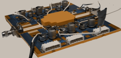
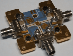
[heading title=”Readily Available Evaluation Boards” type=”h1″ style=”style2″ text_transform=”default” align=”left” margin_bottom=”20″] [heading title=”Solid State Pallet Amplifier Evaluation Board” type=”h3″ style=”style2″ text_transform=”default” align=”left” margin_bottom=”20″] [checklist style=”style1″ icon=”icon-checkmark” ] [item] RF in/out ports (available thru to deembed connnector+launching line structure) [/item] [item] 5 DC voltage channels per side (2 gates, 3 drains with pulsed/no-pulsed drain voltage option) [/item] [item] Pulsed drain with 20-60V amplitude and 15A max peak current (typical) [/item] [item] Min 10 ns t_rise / t_fall, min 1 us pulse width (typical) [/item] [item] Embedded thermocouple [/item] [item] Pallet amplifier footprint 40 mm x 36 mm [/item] [/checklist][heading title=”MMIC Frequency Converter Evaluation Board” type=”h3″ style=”style2″ text_transform=”default” align=”left” margin_bottom=”20″] [checklist style=”style1″ icon=”icon-checkmark” ] [item] 3 RF in/out ports: RF in, IF out, LO in (available thru to deembed connnector+launching line structure) [/item] [item] 4 DC voltage channels (gate/drain for RF LNA, gate/drain for LO buffer) [/item] [item] 2 Control voltage channels (RF VVA control, LO VVA control) [/item] [item] Option for IF DC Blocking capacitor [/item] [item] Embedded thermocouple [/item] [item] Max MMIC converter footprint 2.9 mm x 2.9 mm [/item] [/checklist]
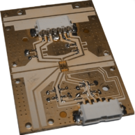
[heading title=”MMIC Single Chip T/R module Evaluation Board” type=”h3″ style=”style2″ text_transform=”default” align=”left” margin_bottom=”20″] [checklist style=”style1″ icon=”icon-checkmark” ] [item] 3 RF in/out ports: RX out, TX in, ANT in/out [/item] [item] 4 DC voltage channels per side (2 gate/drain for TX PA, 2gate/drain for RX LNA) [/item] [item] 2 Control voltage channels for RX/TX switch [/item] [item] Embbedded thru to deembed connnector+launching line structure [/item] [item] Max MMIC TR module footprint 3.2 mm x 3.2 mm [/item] [/checklist]
The available boards can be modified to meet specific requirements
Contact us if you need more details.


